banner

INNOVATION

Technology & Innovation

KEEP THE

ENVIRONMENT

PROTECTED


Project Background


According to the requirements of China’s “Emission standard of pollutants for copper, nickel, cobalt industry” and “Notice on the implementation of special emission limits for air pollutants in some key cities” (No. 2, 2018) by Hubei environmental protection department, from 2020 on, copper, nickel, cobalt industrial enterprises must implement air pollutant emissions according to the new standards, and smoke emissions must be controlled within the scope of the following indicators: SO2≤100mg/m3, smoke and dust ≤10mg/m3, NOx≤100mg/m3. Hubei CEP has formulated this process according to its own actual situation.

System Composition


It is mainly composed of high-efficiency bag filter system, GGH heat exchanger, RTO incineration system, SCR denitrification system and wet deacidification and defogging system, while the place of wet electrostatic precipitator system is reserved at the same time.


Process


1、High-efficiency bag filter system: the raw flue gas of sintering machine enters the bag filter; by adopting high-efficiency bag filter material and reasonable filtration wind speed, the dust content in the flue gas can be below 10mg/Nm3 after going through the bag filter.

2、GGH heat exchanger: in order to save energy, the low-temperature flue gas from the bag filter comes out and the high-temperature flue gas treated by SCR denitrification are heat-exchanged through the GGH heat exchanger.

3、RTO incineration system: organic matter is contained in the raw flue gas of the sintering machine. Through RTO incineration, not only the organic matter in the flue gas can be removed to prevent denitrification below from being affected, but the smoke temperature at the entrance of denitrification device can also be increased to make denitrification reaction take place in an appropriate range.

4、SCR denitrification system: the reducing agent reacts with nitrogen oxides in the high-temperature flue gas under the action of the catalyst, reducing the nitrogen oxides to nitrogen and water, thus achieving the purpose of denitrification.

5、Wet deacidification and defogging system: the flue gas after denitrification enters the heat exchanger again and cools down to 205℃, and then enters the wet desulfurization tower for desulfurization. The fog droplets are removed by high-efficient demister. The content of fog droplets is controlled below 20mg/m3, and the smoke and dust is controlled below 8mg/m3 and discharged through the chimney.


Process characteristics


1、After treatment, the flue gas can meet the requirements of “Notice on the implementation of special emission limits for air pollutants in some key cities” (No. 2, 2018) by Hubei environmental protection department.

2、Long service life of catalyst. After entering the SCR denitrification system, the flue gas has been dedusted to reduce dust and other particles that will block the catalyst micropores, thus prolonging the service life of catalyst.

3、High efficiency of comprehensive utilization of heat energy. After SCR denitrification, the high-temperature flue gas returned to the front end and preheated the flue gas, which reduced the consumption of auxiliary fuel in RTO incineration.


Project Background


As a comprehensive hazardous waste disposal company, Nanjing Company needs a heat carrier with high temperature and convenient temperature adjustment in its comprehensive utilization workshop, but the steam is difficult to meet the requirements, and the operation cost of installing a heat conduction oil furnace is high. Based on its actual situation, Nanjing Company adopts a heat conduction oil furnace and a waste heat recovery system for hazardous waste incineration, which can not only recover the heat from the incineration of flue gas, but also meet the demand of the comprehensive utilization workshop for heat source. It is a domestic initiative that the heat conduction oil furnace is used to recover waste heat from hazardous waste incineration.


System Composition


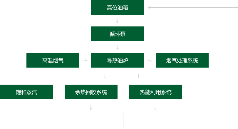
Heat conduction oil furnace system consists of general heat conduction oil furnace, heat conduction oil circulatory system, heat energy utilization system, waste heat recovery system and so on.


Process


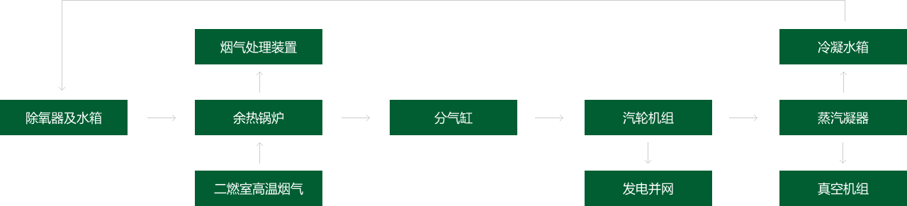
Heat conduction oil furnace: the high-temperature flue gas generated by hazardous waste incineration enters the heat conduction oil furnace, which is used to heat the heat conduction oil while achieving the purpose of cooling the flue gas at the same time. After cooling, the flue gas enters the flue gas treatment system and is discharged up to the standard.


Heat conduction oil circulatory system: heat conduction oil circulator ysystem is composed of circulating pump, top petrol tank, etc. The heat conduction oil at low temperature is transported to the heat conduction oil via circulating pump, and the heat is exchanged with the high-temperature flue gas. The heat conduction oil after heat absorption can be used for the heating of the comprehensive utilization system, and can also generate steam through the waste heat recovery system. The heat conduction oil after cooling is returned to the top petrol tank.


Heat energy utilization system: the heat conduction oil is used as the heat carrier to heat the reaction still and heat exchanger, so that the material can reach the required temperature and the temperature of heat conduction oil is reduced.


Waste heat recovery system: through the heat exchanger (steam generator),the excess heat conduction oil produces saturated steam, which can meet the needs of different heat carriers.


Process characteristics


1、High operating temperature can be obtained under almost constant pressure. It can greatly reduce the operating pressure and safety requirements of the high-temperature heating system and improve the reliability of system and equipment.


2、It can meet the process requirements of heating and cooling at different temperatures within a wider temperature range, or achieve the process requirements of high-temperature heating and low-temperature cooling with the same heat conduction oil in the same system.


3、Two heat carriers, heat conduction oil and steam, can be provided for use in the factory.


Project BackgroundProject Background


Due to the uncertainty of the source of hazardous waste and the complexity of hazardous waste composition, most of the flue gas treatment systems of hazardous waste in the incineration process adopt wet deacidification as the last step of deacidification. Wet deacidification has the characteristic of high efficiency, but there are also problems such as chimney corrosion caused by residual acid gas in flue gas, local influence caused by the falling of saline-alkali particles and water mist, and landscape pollution caused by white plume. The application of wet electrostatic precipitator in the treatment of tail gas from hazardous waste incineration can effectively solve these problems.Due to the uncertainty of the source of hazardous waste and the complexity of hazardous waste composition, most of the flue gas treatment systems of hazardous waste in the incineration process adopt wet deacidification as the last step of deacidification. Wet deacidification has the characteristic of high efficiency, but there are also problems such as chimney corrosion caused by residual acid gas in flue gas, local influence caused by the falling of saline-alkali particles and water mist, and landscape pollution caused by white plume. The application of wet electrostatic precipitator in the treatment of tail gas from hazardous waste incineration can effectively solve these problems.


System Composition


The wet electrostatic precipitator system consists of wet electrostatic precipitator, back flush system and so on.The wet electrostatic precipitator system consists of wet electrostatic precipitator, back flush system and so on.


ProcessProcess


Wet electrostatic precipitator: after SNCR denitrification, emergency cooling, dry/semi-dry deacidification, activated carbon adsorption, bag filter, and wet deacidification and defogging, flue gas enters the wet electrostatic precipitator, where high-voltage corona discharge makes dust, fog droplets and other particles charged, and the charged dust, fog droplets and other particles reach the dust collecting plate/pipe under the action of electric field force, thus achieving the purpose of dedusting.


Back flush system: after being collected in the dust collecting plate/tube, dust, fog droplets and other particles are cleaned regularly to remove the dust with the flow of the scouring fluid. Flushing water is discharged up to the standard after being treated in the sewage treatment station.


Process characteristics


1、Wet electrostatic precipitator is suitable for the treatment of wet flue gas.


2、The wet electrostatic precipitator uses fluid to scour the surface of the collecting plate for dust cleaning, which will not cause the problem of dust floating in the sky again.


3、It can effectively collect fine particles (PM2.5 dust, SO3 acid fog, aerosol), heavy metals (Hg, As, Se, Pb, Cr), organic pollutants (PAHs, PCDD/Fs), etc. The removal efficiency can reach above 90%.


System Design Scale


Saturated steam with a steam inlet flow of 12t/h and pressure of 2.0mpa has a generating capacity of 1250kW.


System Composition


The waste heat power generation system mainly consists of main and auxiliary systems such as waste heat steam power generation system (the main engine of steam turbine, generators, lubricating oil system, etc.), condensed water recovery system (condenser and vacuum unit, etc.), cooling water circulation system (cooling towers, cooling water pump, etc.), and electrical control system (regulating system, safety monitoring system, emergency trip system, etc. of steam turbine).


Waste heat steam power generation system: the waste heat steam generated by the waste heat boiler in the incineration process is distributed into several paths via gas-distributing cylinder and one of them is supplied to the waste heat steam power generation system as the power generation source. The waste heat steam enters the steam turbine to make it work and converts the steam heat energy into shaft power, thus driving the generator to generate power.


Condensed water recovery system: after work is done by the steam turbine, the exhaust steam is sent to the condenser and condensed into the saturated water at the corresponding temperature, which is collected in a unified manner and sent to the condensing water tank for recycling use by the boiler.


Cooling water circulation system: the system is equipped with corresponding cooling tower and cooling water pump to provide cooling circulating water for waste heat power generation system.


Electrical control system: it includes grid-connected cabinet, contact cabinet, auxiliary control cabinet and waste heat power generation governing and protecting system, mainly to complete the allocation of power generated by waste heat power generation system and the adjustment and protection of system operation process.


Process


The waste heat steam power generation system takes the steam generated by the hazardous waste incineration system as the heat source and operates simultaneously with the main incinerator. The steam generated by the waste heat boiler enters the gas-distributing cylinder; one path of steam is used as process steam, and the other path of steam enters into the steam turbine unit to push it to do work and output shaft power, thus driving the generator to generate power. The exhaust steam after work is condensed by the condenser and uniformly collected to the condensing water tank for water supply recycling by the boiler.


Unit Characteristics


1、Wide application. This project adopts a new type of low-grade steam turbine, which can adapt to a wider range of imported steam. Superheated steam, saturated steam and wet steam can all be used as driving steam sources.


2、High safety and stability. The steam separation device is installed in the whole flow passage of the steam turbine, and the outer edge of the steam inlet side of each separator is installed with drainage. After the water droplets leave the moving blade of the previous stage, they will deviate outward along the radial direction under the action of centrifugal force, and are then discharged after entering into the drainage system, thus ensuring the safety and stability of low-grade steam applied in the steam turbine system.


3、High energy efficiency. The flow passage of the steam turbine is optimized for the characteristics of saturated steam with low parameter, which adopts large-diameter impeller, multi-stage expansion and final stage blade laser processing technology, as well as rolling bearing and full speed design to greatly reduce mechanical losses and improve energy utilization efficiency under low-grade steam conditions.


4、Strong applicability under variable conditions. For the characteristic that the fluctuation of low-grade steam parameters leads to frequent stop-start, the design of steam turbine unit is optimized by adopting multi-valve regulation, which can effectively reduce the throttle loss and ensure high efficiency under variable load conditions.


5、High degree of automation. The steam turbine unit is equipped with a powerful governing and protecting system, which can realize one-key start and stop, and the automatic regulating system can quickly adjust related valve action according to the load change, so as to realize the balance between the power of the unit and the characteristics of heat source without the need for monitoring and adjustment by special inspectors to.